|
Technical Overview
1. Introduction |
|
Thousands of audiophiles with sensitive systems, however, dispute this belief, although they may not know exactly why. It is perfectly clear to most audiophiles, and videophiles alike, that cables do indeed have an influence on sound quality (and can even affect video clarity), but how to choose the best cable for any given system remains a mystery In the past few years, several researchers have conducted studies concluding that reactive electrical phenomena affect the transfer of signal through a wire; including inherent resistance, capacitance, and inductance of paired wire sets. Through basic electricity studies, it is quite apparent that inductance affects high frequencies, capacitance affects low frequencies, and resistance impedes the flow of electrical current. Since these reactive elements can vary by several hundred percent, depending on how the wire is geometrically wound, can there be any wonder that different types of wire can sound substantially different? Harmonic Technology offers various lines of cables to provide the finest audio and video signals for any type of system requirement. Patented technologies for refining and casting metals and breakthrough designs for even the newest types of components offer scientifically superior and unprecedented levels of performance. 2. Key Factors Affecting Cables 3. Conductor Metal Harmonic Technology, however, has pioneered a cost effective method of refining metals to obtain purity levels in excess of 99.999997%, allowing a more accurate electrical signal transfer. The purification process is performed in an atmosphere containing no oxygen; thereby greatly reducing the effects of long term oxidization, which is known to degrade performance over long periods of time. Harmonic Technology OCC Single Crystal™ Process versus Typical OFHC Comparison
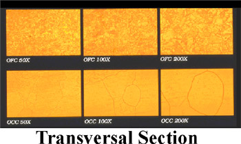
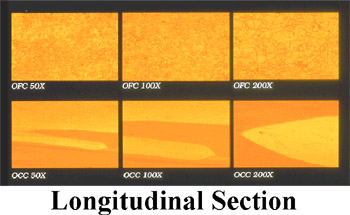
The oxygen content in commercial-grade wire causes progressive oxidation over a period of time, and unfortunately, copper oxide does not conduct electrons. Additional impurities found in commercial copper wire include iron, lead, antimony, arsenic, sulfur, and aluminum. These impurities cause significant distortions to audio and video signals due to the collision of the electrons with the impurities. An audio or video “electron flow” is an incredibly complex signal consisting of both an electrical “flow" and a magnetic field surrounding the wire itself, which contains thousands of packets of information per second. The packets of information contain thousands of different frequencies that combine together to form unique phase structures. The audio, or video, signal is both extremely complex and very delicate, becoming quite susceptible to disruptions in the integrity of the harmonic structure traveling in “waves" on the external surface of the conductors. As such, delivering this complex signal with the least amount of change caused by the wire itself is essential. The elimination of impurities that can cause damage to the signal is very important if accurate sound quality is to be expected. Collisions of the complex electron flow with the impurities are often identified as “harshness,” “brightness,” and/or “veiling and dullness,” as the harmonic structure of the signal has been modified. As altering the complex musical or video signal is considered very undesirable, wire that’s just “good enough" in this case is simply not good enough. Once signal accuracy is lost, it can never be recovered downstream. Harmonic Technology’s unique purity processing eliminates the potential of impurities disrupting the signal and obtains the most accurate signal possible. Another problem with even greater sonic consequences arises from a byproduct of the wire drawing process. When copper slugs are forced through a small die hole to “draw" wire, the copper undergoes a molecular change due to the stress and rapid cool down of the metal. A cross section of wire seen through an electron microscope will show thousands of crystals that have been inadvertently formed in the copper. Approximately 500 crystal boundaries per foot are found in high-grade oxygen-free copper wire and as many as 1,500 boundaries in standard wire. The barriers formed by the crystals become another impediment to the natural flow of electrons in the wire, adding “harshness” and “brightness” to the sound and drastically changing the harmonic structure, altering both image precision and sound stage focus. The crystalline barriers add distortion to the signal, significantly altering the clarity and smoothness desired from audio and video signals. The illustration below shows the electron micrographs of standard wire compared to Harmonic Technology’s Single Crystal™ (OCC) wire. The crystalline barriers are very apparent in the standard wire, and are virtually non-existent in the Harmonic Technology wire. Harmonic Technology’s patented engineering breakthrough eliminates crystalline barriers and offers higher fidelity to the signal. Comparison of OFHC and Harmonic Technology’s Single Crystal ™ (OCC) Structure
A musical note is a fragile balance of minute “fractiles" of sounds, often composed of thousands of different elements. For instance, a grand piano has a felt hammer that strikes a compound string formed of a solid core wire with a wrapping, which vibrates on a brass sounding board and resonates throughout the piano’s hollow body. Each of these elements plays a key role in determining the piano’s “tone." If any of the harmonic overtones are destroyed by the transmission through a playback system, the sound will appear to have an “electronic" quality causing an unpleasant or unrealistic sound. A video transmission from a laserdisc, DVD, digital satellite feed, or VHS tape has a composite signal even more complex than a musical signal. To see the picture in its most realistic form, without any distortion of focus, color, or picture depth, it is highly critical to use wires in your system which do not alter the signal transmission. Thus, the crystal barriers impeding the natural flow of electrons must be eliminated from the wire to allow the signal to flow with complete accuracy. Harmonic Technology has invented a patented, new method where a special process is used to “cast" a single crystal, thereby eliminating crystal barriers. Since the stress of forcing the copper slug through the cold die creates crystal barriers upon the cool-down phase, Harmonic Technology’s new Patented Single Crystal™ (OCC) process is performed by slow-casting the molten, purified copper through a special, preheated machine. The cool-down phase of the single crystal filament is conducted at a very slow rate, to eliminate any unwanted stress crystallization. Single Crystal™ (OCC) Continuous Casting Process
The sonic result of this new technology is pure, natural sound, devoid of the “harshness” and two-dimensional images prevalent in other wires available in the market. Harmonic structure of the music is retained, allowing beautiful timbrel differences between musical instruments to be easily heard along with three-dimensional images of the instruments to be replicated in space. Picture quality is amazingly restored to cinematic quality, looking more like a 70mm film instead of a home video, complete with natural color hues and striking image depth. 4. Insulation 5. Winding Geometry The many differences heard between different brands of interconnects and speaker wires are mainly caused by these reactances and their differing amounts of capacitance versus inductance. These electrical reactances occur because of the interaction between the electrical fields surrounding the transmission path and the alternating electrical current of the current. In crossover design, capacitors are used to block bass signals, while inductors are used to block treble frequencies. To conduct both positive and negative phases of the alternating signal, a pair of conductors may be geometrically situated in several fashions. The individual conductors may be run as a side-by-side pair to allow the positive and negative fields to interact with each other, but it creates high inductance. Alternatively, the pairs may be separated by distance and situated at cross angles to each other, in a woven pattern, to eliminate inductance, but unfortunately increases capacitance. Or, the wire bundles may be set in a circle, with insulation being at the core to hold the wires in symmetry. Although this option is considered better because the geometry may be engineered to reduce both capacitance and inductance, it does not totally eliminate them unless other methods are used in conjunction. The so-called “skin effect” results from the very short high frequency waves traveling on the surface of the wire where there is less resistance to their flow. Conversely, the long wave lengths comprising the low frequencies travel through the core of wire itself. The differences in conduction lead to electrical field differences in the signals, causing phase shift problems at the very high frequencies. An additional phase shift problem occurs when the bass and treble frequencies travel down the wire at slightly different speeds due to the multiple paths a signal can take. This further adds to a lack of coherence between the fundamental tones and their harmonics. An attempt has been made to use ancillary circuits contained in “black boxes" to reduce this distortion. Several competing wire manufacturers have designed RC (resistor/capacitor) networks, which claim to eliminate the phase shift caused by transmission speed differentials and capacitance/inductance effects. In strict engineering terms, these are “band-aid" devices that actually correct a problem caused by inattention to winding geometry and insulation. The RC network boxes, in fact, cause more problems by dissipating the signal and eliminating the needed low level detail of the signal. Moreover, since the speaker’s crossover network is now dependent on the interactions within the RC circuit in the “black box," impedance interactions cause further sonic problems. Many speakers do not sound their best with these “auxiliary" crossover networks interfering with their operation. Harmonic Technology has engineered cables properly from the ground up rather than resorting to auxiliary networks. Our new technology, Balanced Field Geometry™ reduces the cost and provides greater transparency, allowing each speaker system to operate at its highest potential. Many of the leading speaker manufacturers who have discovered the Harmonic Technology difference now use Harmonic Technology cables in their reference systems. After several years of applied research, Harmonic Technology has engineered a technique to reduce both inductance and capacitance to theoretical levels, allowing an almost perfect transmission path without alteration of the signal. The proprietary technology consists of “spiraling" the separated bundles of positive and negative phase wires with a hollow tubular core as a former. The insulated bundles are both twisted and then spiraled in alternating fashion, which reduces both capacitance and inductance, while simultaneously allowing both short and long wavelengths to travel down the wire at equal speeds. This technique reduces phase shift problems to inaudible levels within the audio range. Balanced Field Geometry ™ allows for perfectly neutral frequency response along with very fast transient response, reproducing the signal as close to perfection as possible. This method also rejects radio frequency interference, further providing a quieter signal with a “black" and silent background. 6. Connectors
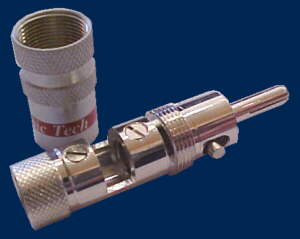
The RCA plugs feature a locking outer barrel, which can be twisted to increase tension. These plugs can also be used as a “tuning" device to alter the size of specific images within the sound stage. In addition, the tip of the plug has been designed to fit very tightly. All joints are mechanically compressed before solder is applied to ensure a strong bond and prevent breakage during any movement. The mechanically, cold-welded compression fitting also allows for better electron flow, as solder alone does not conduct electricity as well. 7. New Photon Technology Harmonic Technology’s LAM takes an analog signal and immediately converts it to light to avoid any unnecessary digitization and transmits that signal through an audio-grade fiber optic link. How does the LAM work? What is the result? |